Superceeded by NJQRP's Excellent DDS board kit
My DDS based on the AN9850
==========================
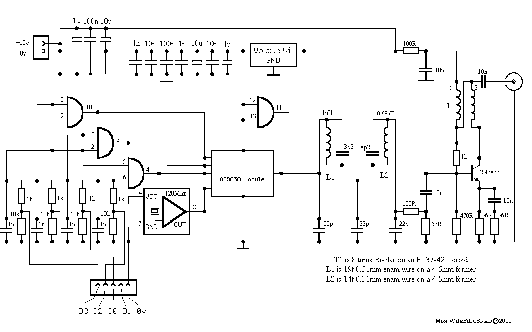
This DDS is based on two designs, The RF side and SMD approach is from the Analog Devices Application Note AN557. The Logic side of the DDS is based on Peter OM3CPH's design, All URL's are at the bottom of this page. The only reason for doing it this way was my dislike of working with surface mount components and AN557 showed me how I could simplify the SMD side of things. The AD9850 really is a SMALL chip (28pins in roughly the same area as a 741 op-amp's 8pins). I used a Weller TCP soldering iron, 22swg multicore solder and a Magnifying glass taken from an old slide Projector plus a hand-steadying sip of Woods Navy Rum to construct the DDS Module. With care it is really quite easy to do the SMD side of things, I'm now working on a similar 'Header' style approach for the AD9852. Anyway..
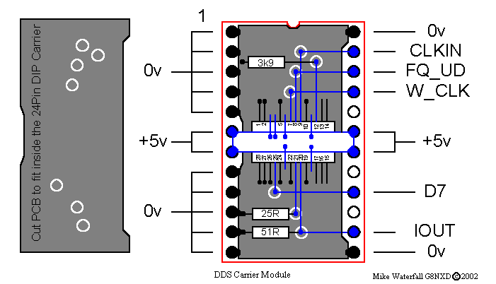
The DDS Carrier Module
======================
The DDS module is based on Analog Devices Application Note AN557.PDF ( previously published in the Radio Society of Great Britain's publication RADCOM in January through April 1999 ).
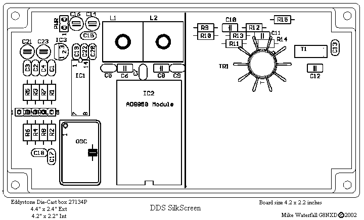
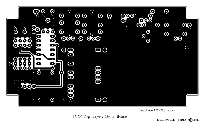
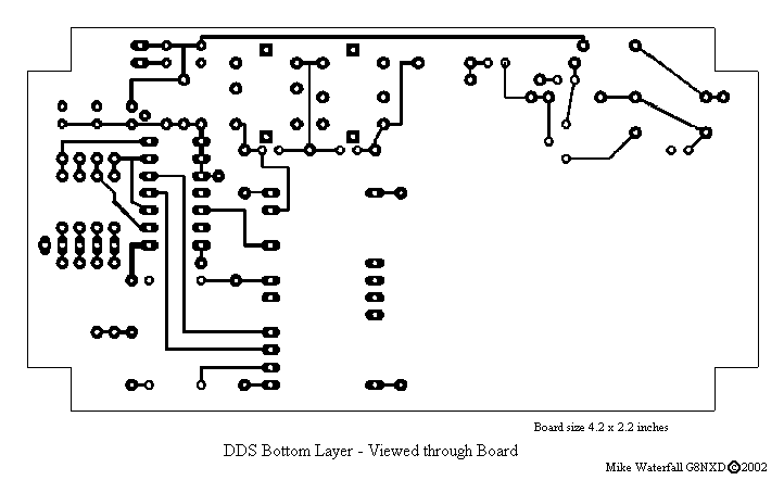
In my version, I did'nt have a 28pin Header so I used a 24pin header instead. I also added a few small insulated lands which make it easier to deal with the point to point wiring. These lands can be seen as white circles on the PCB. All connections are indicated by blobs, if there is'nt a blob there is'nt a connection. The Blue rectangle is the +5v rail connected between pins 6/7 and 18/19 of the DIL header, it is a piece of copper foil 0.2 inches wide, glued to the top of the AD9850 as per AN557. The blue wires are 30swg point to point wiring. Copious decoupling capacitors are added between the +5v foil and the groundplane after the module has been tested.
I acknowledge Peter Halicky OM3CPH as the original author of the Digital side of this DDS Peter Rhodes G3XJP for AN557 and the original author of the RF side of this DDS. My thanks to them both.
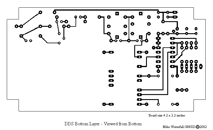
This is the link to the DDS_NXD.ZIP file of the diagrams, PCB layouts etc. I retain copyright on the PCB and DDS Header Layout. Reproduction for non-commercial use is welcomed.
The PCB and DDS Header were designed by myself using Freeware Eagle 4.01 from Cadsoft and the Eagle files of the PCB, albiet untidily presented, are included in the zip file
Links to OM3CPH, AN557 and Freeware Eagle 4.01 are...
OM3CPH's site for article and Software
Analog Devices Application Note AN557.PDF
Cadsoft's website for Eagle 4.01 Software
![]()