
Using a GDO
===========
This page describes how to use a GDO or Grid Dip Oscillator. Most of the description and the diagrams were taken from an old User Manual published by Barker and Williamson of Pensylvania in, I would guess, about 1952. If they or anyone holding the copyright wishes me to remove this page then I will do so. If anyone notices any errors, spelling or otherwise, please let me know, my e-mail address is on my home page
LC Circuits
===========
The main use of the instrument when used as a dip meter is to
indicate the resonant frequency of a tuned circuit. This is done
by placing the coil of the instrument in close inductive
proximity to the coil of the circuit being measured, and rotating
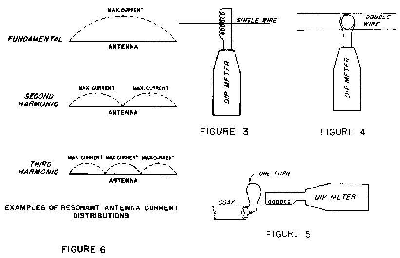
the tuning knob until a sharp dip is noted in the meter. See Fig1
and Fig2.


The sensitivity control is used to keep the meter reading
approximately in mid scale. When the position of the meter dip is
ascertained, the coil distance is increased until the dip is
barely disernable. The resonant frequency of the circuit being
measured can then be approximated from the appropriate dial
scale, and accurately measured with a Digital Frequency Meter or
by locating the signal on a calibrated reciever.
The above procedure is used in finding the resonant frequency of:
1. Traps and chokes
2. Tank circuits
3. I.F. circuits
4. R.F. circuits
5. Filters (high, low and band-pass) etc.
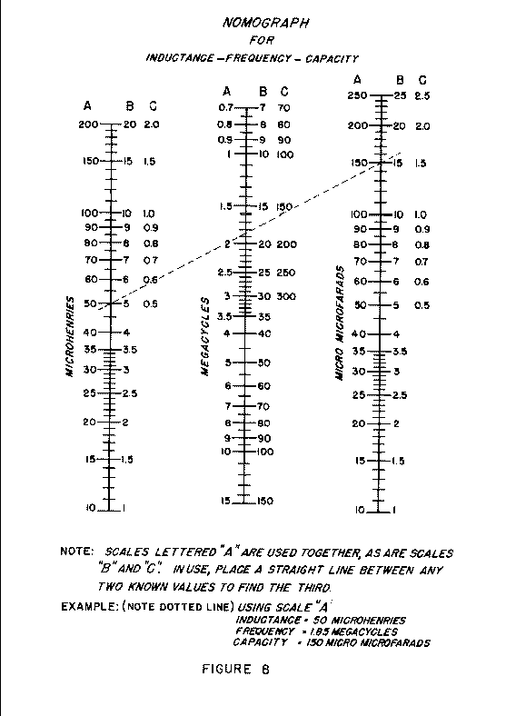
After the resonant frequency of a tuned circuit has been determined, the inductance or capacitance may be found if one or the other is known. The nomograph (see fig8) relating inductance, capacitance and frequency has been prepared to facilitate this procedure or it can be calculated using the formulae:
L = 25400 / (f*f)*C or C = 25400 / (f*f)*L or f = 1 / 6.284*(square root of (L*C))
where f is Frequency in Mhz, C is in Picofarads, L is in microHenries.

Known values of capacity can be purchased for use as
standards, or established by the use of known values of
inductance. Standard inductances can be fabricated by using
standard capacitors.
Note that the approximate "Q" or quality of resonant
circuits may be compared by observing the sharpness of the meter
dip as the tuning is rotated through resonance. A sharp dip
indicates a circuit of higher "Q" than one with a broad
dip.
When used on transistor equipment it may be useful to either
isolate the circuit under test or to use the instrument as an
Adsorbtion Wave Meter, see later, and have the circuit under test
operating, this is due to the low impeadances often seen in
semiconductor circuits.
Antennas and Transmission Lines
===============================
Antennas and transmission lines differ from lumped LC circuits in
that the inductance and capacity is distributed. It is important
to remember that more than one resonant frequency is present
which must be taken into concideration. It is advantageous to
determine in advance the approximate frequencies of interest and
sketch the antenna and transmission line set-up in terms of
current distribution.
Generally, the resonant frequency of an antenna is measured by
coupling the coil of the instrument to the part of the antenna
with a current maximum. Although points of voltage maximum may be
used, they are best avoided due to the increased possibility of
spurious dips. See fig3-6.

The adjustment of the instrument is then the same as for LC
circuits. For example, the halfwave antenna has a current maximum
at the centre. The driven element in a beam antenna is usually a
halfwave. When its frequency is to be determined, it is nessesary
to disconnect all feeders and short out all breaks so introduced.
An antenna may also be operated on any multiple of its
fundamental frequency. When this operation is desired, it is
clarifying to sketch the current variation along the length of
the antennae and make the frequency determination at one of the
points of current maximum. For this frequency determination it is
also nessesary to disconnect all transmission lines and short out
any breaks.
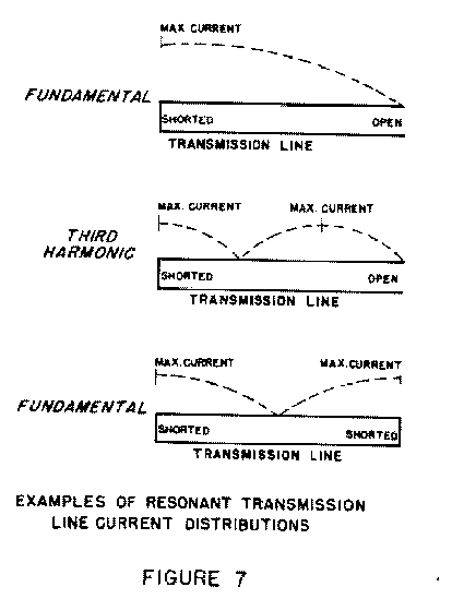
The resonant frequency of a transmission line may be measured by
concidering it as similar to the folded section of an antenna.
The instrument is coupled to a shorted end of the transmission
line and measurement is made as for an LC circuit. A sketch of
the probable current distribution is helpful in determining the
harmonic mode of operation. See fig7

. For instance a quarterwave transmission line with the far
end open is similar to a halfwave antennae and resonances will be
found approximately at odd multiples of the fundamental
frequency. When a transmission line is shorted at the far end, it
may be concidered as two quarterwave transmission lines placed
back to back. The resonant frequency is then approximately twice
that found with the far end open.
When the transmission line is terminated in a pure resistance
equal to its characteristic impedance, it will be found that the
resonances will disappear. Any other load will cause resonances
to reappear except at those frequencies at which the load on the
transmission line is equal to its characteristic impedance. These
facts can be used to load a transmission line to a high degree of
accuracy.
Signal Generator
================
The instrument can be used as a source of signal in primary
alignment of recievers. The amount of pickup by the reciever is
varied by adjusting the position or distance of the instrument.
The output signal is unmodulated, so that an R.F type of signal
tracer is nessesary for indication the proper alignment of the
tuned circuits. The "S" meter, in some recievers, may
be used as an indicating device for alignment as long as the
signal is kept at a low value to prevent AGC action, or the AGC
may be disabled during alignment. If the instrument has a
modulating facility then an audio type signal tracer may be used
for alignment.
The instrument is a conveniant, if unstable, source of marker
signals when using a sweep generator or Wobbulator. In this case
also, the intensity of the marker may be varied by adjusting the
position or distance of the instrument from the circuit under
test.
For isolation, markers and test signals may be fed to various
circuits by means of a transmission line. The input of the
transmission line should be shorted with a loop , Fig5, that is
lightly coupled to the coil in the instrument. The output of the
transmission line is then fed into the equipment under test by
any convenient means.
Signal Intensity Meter and Monitor
==================================
( Diode switch ON, if fitted. )
In this case, the instrument functions as an R.F. Pickup device
or an Absorbtion Wavemeter where the meter deflection is
proportional to the signal being picked up by the coil. The
sensitivity may be increased by coupling the coil of the
instrument to an antenna or transmission line extension, Fig5. As
a signal intensity or field strength meter, the instrument is
useful in:
1. Relative Field strength measurements
2. Neutralisation of amplifiers
3. Harmonic and parasitic analysis
4. Investigating standing waves on open line feeders
Inserting a phone jack into the "phone socket" usually disconnects the meter and enables modulation on the incoming signal to be heard. The instrument may then be used for determination of:
1. Hum and noise
2. Distortion
3. Audio quality
When used in this mode extreme care is needed to prevent electrocution when working on high energy circuits
Special Uses 1a,1b - Measuring Mutual Inductance and Coupling
Coefficient
=========================================================================
Connect the two coils in series and the combination across a
standard capacitor. Measure the resonant frequency and determine
the the combined inductance as outlined in an earlier paragraph
under "Applications - LC circuits". The connections to
one of the coils is then reversed and the inductance of the
combination is again determined. The effective mutual inductance
M between the the two coils is equal to one fourth the difference
between the two resultant measurements.
Having determined M from the above paragraph. Measure the
inductance of each coil leaving the other coil open circuit. The
coefficient of coupling K is given by the following formula:
K= M/ square root of(L1*L2)
where M is the mutual inductance and L1, L2 are the self inductances of the two coils respectivly.
Special uses 2 - Measurement of Coax length
===========================================
Open circuit one end of the cable and short the other end with a
short loop and couple the instrument to this loop, see Fig5, then
starting at the lowest frequency, note the frequency of the
successive dips. The fundamental resonanant frequency ( based on
a quarterwave ) is approximately equal to one half the difference
between two successive dips.
The physical length of the cable may now be calculated by the
following formula:
L =(246*k)/f
where L is the length in feet, f is the resonant frequency in Mhz and k is the velocity factor of the cable ( usually 0.66 for solid dielectric ). It follows that the Velocity factor k can also be determined if the length of the cable is known.
Special uses 3 - crystal tester/marker
======================================
In many instruments the design is such that if a crystal is
inserted in the coil socket it will oscillate at its fundamental
frequency and an indication of oscillation will be given on the
dip meter, crystal activity can be estimated by the amount of
deflection. This signal is far more stable than useing a Coil and
can be used as a Marker signal